How good is what?

Geology is a descriptive science, which is to say, geologists are label-makers. We record observations by assigning labels to data. Labels can either be numbers or they can be words. As such, of the numerous tasks that machine learning is fit for attacking, supervised classification problems are perhaps the most accessible – the most intuitive – for geoscientists. Take data that already has labels. Build a model that learns the relationships between the data and labels. Use that model to make labels for new data. The concept is the same whether a geologist or an algorithm is doing it, and in both cases we want to test how well our classifier is at doing its label-making.

2d_2class_classifier_left.png

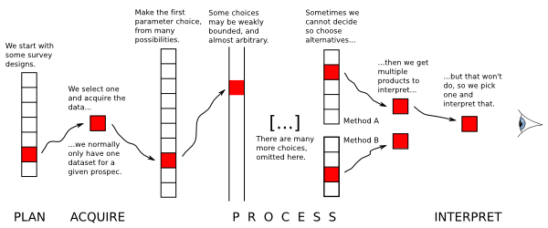
Say we have a classifier that will tell us whether a given combination of rock properties is either a dolomite (purple) or a sandstone (orange). Our classifier could be a person named Sally, who has seen a lot of rocks, or it could be a statistical model trained on a lot of rocks (e.g. this one on the right). For the sake of illustration, say we only have two tools to measure our rocks – that will make visualizing things easier. Maybe we have the gamma-ray tool that measures natural radioactivity, and the density tool that measures bulk density. Give these two measurements to our classifier, and they return to you a label. 

How good is my classifier?

Once you've trained your classifier – you've done the machine learning and all that – you've got yourself an automatic label maker. But that's not even the best part. The best part is that we get to analyze our system and get a handle on how good we can expect our predictions to be. We do this by seeing if the classifier returns the correct labels for samples that it has never seen before, using a dataset for which we know the labels. This dataset is called validation data.

Using the validation data, we can generate a suite of statistical scores to tell us unambiguously how this particular classifier is performing. In scikit-learn, this information compiled into a so-called classification report, and it’s available to you with a few simple lines of code. It’s a window into the behaviour of the classifier that warrants deeper inquiry.

To describe various elements in a classification report, it will be helpful to refer to some validation data:

Our Two-class Classifier (left) has not seen the Validation Data (middle). We can calculate a classification report by Analyzing the intersection of the two (right).

Our Two-class Classifier (left) has not seen the Validation Data (middle). We can calculate a classification report by Analyzing the intersection of the two (right).

Accuracy is not enough

When people straight up ask about a model’s accuracy, it could be that they aren't thinking deeply enough about the performance of the classifier. Accuracy is a measure of the entire classifier. It tells us nothing about how well we are doing with one class compared to another, but there are other metrics that tell us this:

metric_definitions2.png

Support — how many instances there were of that label in the validation set.

Precision — the fraction of correct predictions for a given label. Also known as positive predictive value.

Recall — the proportion of the class that we correctly predicted. Also known as sensitivity.

F1 score — the harmonic mean of precision and recall. It's a combined metric for each class.

Accuracy – the total fraction of correct predictions for all classes. You can calculate this for each class, but it will be the same value for each of the class.   

DIY classification report

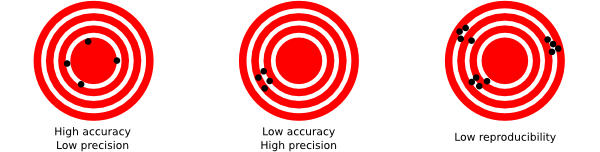
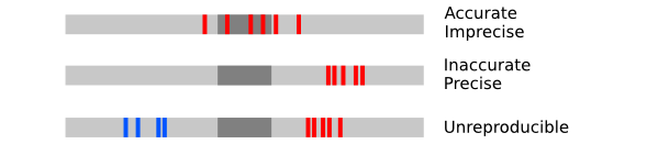
If you're like me and you find the grammar of true positives and false negatives confusing, it might help to to treat each class within the classifier as its own mini diagnostic test, and build up data for the classification report row by row. Then it's as simple as counting hits and misses from the validation data and computing some fractions. Inspired by this diagram on the Wikipedia page for the F1 score, I've given both text and pictorial versions of the equations:

dolomite_and_classifier_report_sheet.png

Have a go at filling in the scores for the two classes above. After that, fill in your answers into your own hand-drawn version of the empty table below. Notice that there is only a single score for accuracy for the entire classifier, and that there may be a richer story between the various other scores in the table. Do you want to optimize accuracy overall? Or perhaps you care about maximizing recall in one class above all else? What matters most to you? Should you penalize some mistakes stronger than others?

clf_report.png

When data sets get larger – by either increasing the number of samples, or increasing the dimensionality of the data – even though this scoring-by-hand technique becomes impractical, the implementation stays the same. In classification problems that have more than two classes we can add in a confusion matrix to our reporting, which is something that deserves a whole other post. 

Upon finishing logging a slab of core, if you were to ask Sally the stratigrapher, "How accurate are your facies?", she may dismiss your inquiry outright, or maybe point to some samples she's not completely confident in. Or she might tell you that she was extra diligent in the transition zones, or point to regions where this is very sandy sand, or this is very hydrothermally altered. Sadly, we in geoscience – emphasis on the science – seldom take the extra steps to test and report our own performance. But we totally could.

The ANSWERS. Upside Down. To two Decimal places.

The ANSWERS. Upside Down. To two Decimal places.

The curse of hunting rare things

What are the chances of intersecting features with a grid of cross-sections? I often wonder about this when interpreting 2D seismic data, but I think it also applies to outcrops, or any other transects. I want to know:

  1. If there are only a few of these features, how many should I see?
  2. What's the probability of the lines missing them all? 
  3. Conversely, if I interpret x of them, then how many are there really?
  4. How is the detectability affected by the reliability of the data or my skills?

I used to have a spreadsheet for computing all this stuff, but spreadsheets are dead to me so here's an IPython Notebook :)

An example

I'm interpreting seep locations on 2D data at the moment. So I'm looking for subvertical pipes and chimneys, mud volcanos, seafloor pockmarks and pingos, that sort of thing (see Løseth et al., 2009 for a great overview). Here are some similar features from the Norwegian continental shelf from Hustoft et al., 2010:

Figure 3 from hustoft et al. (2010) showing the 3D expression of some hydrocarbon leakage features in Norway. © The Authors.

As Hustoft et al. show, these can be rather small features — most pockmarks are in the 100–800 m diameter range, so let's call it 500 m. The dataset I have is an orthogonal grid of decent quality 2D lines with a 3 km spacing. The area is about 120,000 km². For the sake of argument (and a forward model), let's imagine there are 120 features I'm interested in — one per 1000 km². Here's a zoomed-in view showing a subset of the problem:

Zoomed-in view of part of my example. A grid of 2D seismic lines, 3 km apart, and randomly distributed features, each 500 m in diameter. If a feature's centre falls inside a grey square, then the feature is not intersected by the data. The grey squa…

Zoomed-in view of part of my example. A grid of 2D seismic lines, 3 km apart, and randomly distributed features, each 500 m in diameter. If a feature's centre falls inside a grey square, then the feature is not intersected by the data. The grey squares are 2.5 km across.

According to my calculations...

  1. Of the 120 features in the area, we expect 37 to be intersected by the data. Of course, some of those intersections might be very subtle, if they are right at the edge of the feature.
  2. The probability of intersecting a given feature is 0.31. There are 120 features, so the probability of the whole dataset intersecting at least one is essentially 1 (certain). That's good! Conversely, the probability of missing them all is effectively 0. (If there were only 5 features, then there'd be about a 16% chance of missing them all.)
  3. Clearly, if I interpret 37 features, there are about 120 in total (that was my a priori). It's a linear relationship, so if I interpret 10 features, I can expect there to be about 33 altogether, and if I see 100 then I can expect that there are almost 330 in total. (I think the probability distribution would be log-normal, but would appreciate others' insights here.)
  4. Reliability? That sounds like a job for Bayes' theorem...

It's far from certain that I will interpret everything the data intersects, for all sorts of reasons:

  • I am human and therefore inconsistent, biased, and fallible.
  • The feature may be cryptic in the section , because of how it was intersected.
  • The data may be poor quality at that point, or everywhere.

Let's assume that if a feature has been intersected by the data, then I have a 75% chance of actually interpreting it. Bayes' theorem tells us how to update the prior probability of 0.31 (for a given feature; point 2 above) to get a posterior probability. Here's the table:

Interpreted Not interpreted
Intersected by a 2D line 28 9
Not intersected by any lines 21 63

What do the numbers mean?

  • Of the 37 intersected features, I interpret 28.
  • I fail to interpret 9 features that are intersected by the data. These are Type II errors, false negatives.
  • I interpret another 21 features which are not real! These are Type I errors: false positives. 
  • Therefore I interpret 48 features, of which only 57% are real. This seems like a lot, but it's a function of my imperfect reliability (75%) and the poor sampling, resulting in a large number of 'missed' features.

Interestingly, my 75% reliability translates into a 57% chance of being right about the existence of a feature. We've seen this effect before — it's the curse of hunting rare things: with imperfect knowledge, we are often wrong


References

Hustoft, S, S Bünz, and J Mienart (2010). Three-dimensional seismic analysis of the morphology and spatial distribution of chimneys beneath the Nyegga pockmark field, offshore mid-Norway. Basin Research 22, 465–480. DOI 10.1111/j.1365-2117.2010.00486.x 

Løseth, H, M Gading, and L Wensaas (2009). Hydrocarbon leakage interpreted on seismic data. Marine & Petroleum Geology 26, 1304–1319. DOI 10.1016/j.marpetgeo.2008.09.008 

Pick This! Social interpretation

PIck This is a new web app for social image interpretation. Sort of Stack Exchange or Quora (both awesome Q&A sites) meets Flickr. You look for an interesting image and offer your interpretation with a quick drawing. Interpretations earn reputation points. Once you have enough rep, you can upload images and invite others to interpret them. Find out how others would outline that subtle brain tumour on the MRI, or pick that bifurcated fault...

A section from the Penobscot 3D, offshore Nova Scotia, Canada. Overlain on the seismic image is a heatmap of interpretations of the main fault by 26 different interpreters. The distribution of interpretations prompts questions about what is 'the' an…

A section from the Penobscot 3D, offshore Nova Scotia, Canada. Overlain on the seismic image is a heatmap of interpretations of the main fault by 26 different interpreters. The distribution of interpretations prompts questions about what is 'the' answer. Pick this image yourself at pickthis.io.

The app was born at the Geophysics Hackathon in Denver last year. The original team consisted of Ben Bougher, a UBC student and long-time Agile collaborator, Jacob Foshee, a co-founder of Durwella, Chris Chalcraft, a geoscientist at OpenGeoSolutions, Agile's own Evan Bianco of course, and me ordering pizzas and googling domain names. By demo time on Sunday afternoon, we had a rough prototype, good enough for the audience to provide the first seismic interpretations.

Getting from prototype to release

After the hackathon, we were very excited about Pick This, with lots of ideas for new features. We wanted it to be easy to upload an image, being clear about its provenance, and extremely easy to make an interpretation, right in the browser. After some great progress, we ran into trouble bending the drawing library, Raphael.js, to our will. The app languished until Steve Purves, an affable geoscientist–programmer who lives on a volcano in the middle of the Atlantic, came to the rescue a few days ago. Now we have something you can use, and it's fun! For example, how would you pick this unconformity

This data is proprietary to MultiKlient Invest AS. Licensed CC-BY-SA. 

This data is proprietary to MultiKlient Invest AS. Licensed CC-BY-SA. 

This beautiful section is part of this month's Tutorial in SEG's The Leading Edge magazine, and was the original inspiration for the app. The open access essay is by Don Herron, the creator of Interpreter Sam, and describes his approach to interpreting unconformities, using this image as the partially worked example. We wanted a way for readers to try the interpretation themselves, without having to download anything — it's always good to have a use case before building something new. 

What's next for Pick This?

I'm really excited about the possibilities ahead. Apart from the fun of interpreting other people's data, I'm especially excited about what we could learn from the tool — how long do people spend interpreting? How many edits do they make before submitting? And we'd love to add other modes to the tool, like choosing between two image enhancement results, or picking multiple features. And these possibilities only multiply when you think about applications outside earth science, in medical imaging, remote sensing, or astronomy. So much to do, so little time! 

We trust your opinion. Maybe you can help us:

  • Is Pick This at all interesting or fun or useful to you? Is there a use case that occurs to you? 
  • Making the app better will take time and therefore money. If your organization is interested in image enhancement, subjectivity in interpretation, or machine learning, then maybe we can work together. Get in touch!

Whatever you do, please have a look at Pick This and let us know what you think.

R is for Resolution

Resolution is becoming a catch-all term for various aspects of the quality of a digital signal, whether it's a photograph, a sound recording, or a seismic volume.

I got thinking about this on seeing an ad in AAPG Explorer magazine, announcing an 'ultra-high-resolution' 3D in the Gulf of Mexico (right), aimed at site-survey and geohazard detection. There's a nice image of the 3D, but the only evidence offered for the 'ultra-high-res' claim is the sample interval in space and time (3 m × 6 m bins and 0.25 ms sampling). This is analogous to the obsession with megapixels in digital photography, but it is only one of several ways to look at resolution. The effect of increasing the sample interval of some digital images is shown in the second column here, compared to 200 × 200 pixels originals (click to zoom):

Another aspect of resolution is spatial bandwidth, which gets at resolving power, perhaps analogous to focus for a photographer. If the range of frequencies is too narrow, then broadband features like edges cannot be represented. We can simulate poor frequency content by bandpassing the data, for example smoothing it with a Gaussian filter (column 3).

Yet another way to think about resolution is precision (column 4). Indeed, when audiophiles talk about resolution, they are talking about bit depth. We usually record seismic with 32 bits per sample, which allows us to discriminate between a large number of values — but we often view seismic with only 6 or 8 bits of precision. In the examples here, we're looking at 2 bits. Fewer bits means we can't tell the difference between some values, especially as it usually results in clipping.

If it comes down to our ability to tell events (or objects, or values) apart, then another factor enters the fray: signal-to-noise ratio. Too much noise (column 5) impairs our ability to resolve detail and discriminate between things, and to measure the true value of, say, amplitude. So while we don't normally talk about the noise level as a resolution issue, it is one. And it may have the most variety: in seismic acquisition we suffer from thermal noise, line noise, wind and helicopters, coherent noise, and so on.

I can only think of one more impairment to the signals we collect, and it may be the most troubling: the total duration or extent of the observation (column 6). How much information can you afford to gather? Uncertainty resulting from a small window is the basis of the game Name That Tune. If the scale of observation is not appropriate to the scale we're interested in, we risk a kind of interpretation 'gap' — related to a concept we've touched on before — and it's why geologists' brains need to be helicoptery. A small 3D is harder to interpret than a large one. 

The final consideration is not a signal effect at all. It has to do with the nature of the target itself. Notice how tolerant the brick wall image is to the various impairments (especially if you know what it is), and how intolerant the photomicrograph is. In the astronomical image, the galaxy is tolerant; the stars are not. Notice too that trying to 'resolve' the galaxy (into a point, say) would be a mistake: it is inherently low-resolution. Indeed, its fuzziness is one of its salient features.

Have I missed anything? Are there other ways in which the recorded signal can suffer and targets can be confused or otherwise unresolved? How does illumination fit in here, or spectral bandwidth? What do you mean when you talk about resolution?


This post is an exceprt from my talk at SEG, which you can read about in this blog post. You can even listen to it if you're really bored. The images were generated by one of my IPython Notebooks that I point to in the talk, specifically images.ipynb

Astute readers with potent memories will have noticed that we have skipped Q in our A to Z. I just cannot seem to finish my post about Q, but I will!

The Safe Band ad is copyright of NCS SubSea. This low-res snippet qualifies as fair use for comment.

More AAPG highlights

Here are some of our highlights from the second half of the AAPG Annual Convention in Houston.

Conceptual uncertainty in interpretation

Fold-thrust belt, offshore Nigeria. Virtual Seismic Atlas.Rob Butler's research is concerned with the kinematic evolution of mountain ranges and fold thrust belts in order to understand the localization of deformation across many scales. Patterns of deformed rocks aren't adequately explained by stress fields alone; they are also controlled by the mechancial properties of the layers themselves. Given this fact, the definition of the layers becomes a doubly important part of the interpretation.

The biggest risk in structural interpretation is not geometrical accuracy but whether or not the concept is correct. This is not to say that we don't understand geologic processes. Rather, a section can always be described in more than one way. It is this risk in the first order model that impacts everything we do. To deal with conceptual uncertainty we must first capture the range, otherwise it is useless to do any more refinement. 

He showed a crowd-sourced compiliation of 24 interpretations from the Virtual Seismic Atlas as a way to stack up a series of possible structural frameworks. Fifteen out of twenty-four interviewees interpreted a continuous, forward-propagating thrust fault as the main structure. The disagreements were around the existence and location of a back thrust, linkage between fore- and back-thrusts, the existence and location of a detachment surface, and its linkage to the fault planes above. Given such complexity, "it's rather daft," he said, "to get an interpretation from only one or two people." 

CT scanning gravity flows

Mike Tilston and Bill Arnott gave a pair of talks about their research into sediment gravity flows in the lab. This wouldn't be newsworthy in itself, but their 2 key innovations caught our attention: 

  1. A 3D velocity profiler capable of making 23 measurements a second
  2. The flume tank ran through a CT scanner, giving a hi-res cross-section view

These two methods sidestep the two major problems with even low-density (say 4% by weight) sediment gravity flows: they are acoustically attenuative, and optically opaque. Using this approach Tilston and Arnott investigated the effect of grain size on the internal grain distribution, finding that fine-grained turbidity currents sustain a plug-like wall of sediment, while coarse-grained flows have a more carpet-like distribution. Next, they plan to look at particle shape effects, finer grain sizes, and grain mixtures. Technology for the win!

Hypothesizing a martian ocean

Lorena Moscardelli showed topograhic renderings of the Eberswalde delta (right) on the planet Mars, hypothesizing that some martian sedimentary rocks have been deposited by fluvial processes. An assertion that posits the red planet with a watery past. If there are sedimentary rocks formed by fluids, one of the fluids could have been water. If there has been water, who knows what else? Hydrocarbons? Imagine that! Her talk was in the afternoon session on Space and Energy Frontiers, sandwiched by less scientific speakers raising issues for staking claims and models for governing mineral and energy resources away from earth. The idea of tweaking earthly policies and state regulations to manage resources on other planets, somehow doesn't align with my vision of an advanced civilization. But the idea of doing seismic on other planets? So cool.

Poster gorgeousness

Matt and I were both invigorated by the quality, not to mention the giant size, of the posters at the back of the exhibition hall. It was a place for the hardcore geoscientists to retreat from the bright lights, uniformed sales reps, and the my-carpet-is-cushier-than-your-carpet marketing festival. An oasis of authentic geoscience and applied research.

We both finally got to meet Brian Romans, a sedimentologist at Virginia Tech, amidst the poster-paneled walls. He said that this is his 10th year venturing to the channel deposits that crop out in the Magallanes Basin of southern Chile. He is now one of the three young, energetic profs behind the hugely popular Chile Slope Systems consortium.

Three years ago he joined forces with Lisa Stright (University of Utah), and Steve Hubbard (University of Calgary) and formed the project investigating processes of sediment transfer across deepwater slopes exposed around Patagonia. It is a powerhouse of collaborative research, and the quality of graduate student work being pumped out is fantastic. Purposeful and intentional investigations carried out by passionate and tech-savvy scientists. What can be more exciting than that?

Do you have any highlights of your own? Please leave a note in the comments.

What is the Gabor uncertainty principle?

This post is adapted from the introduction to my article Hall, M (2006), Resolution and uncertainty in spectral decomposition. First Break 24, December 2006. DOI: 10.3997/1365-2397.2006027. I'm planning to delve into this a bit, partly as a way to get up to speed on signal processing in Python. Stay tuned.


Spectral decomposition is a powerful way to get more from seismic reflection data, unweaving the seismic rainbow.There are lots of ways of doing it — short-time Fourier transform, S transform, wavelet transforms, and so on. If you hang around spectral decomposition bods, you'll hear frequent mention of the ‘resolution’ of the various techniques. Perhaps surprisingly, Heisenberg’s uncertainty principle is sometimes cited as a basis for one technique having better resolution than another. Cool! But... what on earth has quantum theory got to do with it?

A property of nature

Heisenberg’s uncertainty principle is a consequence of the classical Cauchy–Schwartz inequality and is one of the cornerstones of quantum theory. Here’s how he put it:

At the instant of time when the position is determined, that is, at the instant when the photon is scattered by the electron, the electron undergoes a discontinuous change in momen- tum. This change is the greater the smaller the wavelength of the light employed, i.e. the more exact the determination of the position. At the instant at which the position of the electron is known, its momentum therefore can be known only up to magnitudes which correspond to that discontinuous change; thus, the more precisely the position is determined, the less precisely the momentum is known, and conversely. — Heisenberg (1927), p 174-5.

The most important thing about the uncertainty principle is that, while it was originally expressed in terms of observation and measurement, it is not a consequence of any limitations of our measuring equipment or the mathematics we use to describe our results. The uncertainty principle does not limit what we can know, it describes the way things actually are: an electron does not possess arbitrarily precise position and momentum simultaneously. This troubling insight is the heart of the so-called Copenhagen Interpretation of quantum theory, which Einstein was so famously upset by (and wrong about).

Dennis Gabor (1946), inventor of the hologram, was the first to realize that the uncertainty principle applies to signals. Thanks to wave-particle duality, signals turn out to be exactly analogous to quantum systems. As a result, the exact time and frequency of a signal can never be known simultaneously: a signal cannot plot as a point on the time-frequency plane. Crucially, this uncertainty is a property of signals, not a limitation of mathematics.

Getting quantitative

You know we like the numbers. Heisenberg’s uncertainty principle is usually written in terms of the standard deviation of position σx, the standard deviation of momentum σp, and the Planck constant h:

In other words, the product of the uncertainties of position and momentum is small, but not zero. For signals, we don't need Planck’s constant to scale the relationship to quantum dimensions, but the form is the same. If the standard deviations of the time and frequency estimates are σt and σf respectively, then we can write Gabor’s uncertainty principle thus:

So the product of the standard deviations of time, in milliseconds, and frequency, in Hertz, must be at least 80 ms.Hz, or millicycles. (A millicycle is a sort of bicycle, but with 1000 wheels.)

The bottom line

Signals do not have arbitrarily precise time and frequency localization. It doesn’t matter how you compute a spectrum, if you want time information, you must pay for it with frequency information. Specifically, the product of time uncertainty and frequency uncertainty must be at least 1/4π. So how certain is your decomposition?

References

Heisenberg, W (1927). Über den anschaulichen Inhalt der quantentheoretischen Kinematik und Mechanik, Zeitschrift für Physik 43, 172–198. English translation: Quantum Theory and Measurement, J. Wheeler and H. Zurek (1983). Princeton University Press, Princeton.

Gabor, D (1946). Theory of communication. Journal of the Institute of Electrical Engineering 93, 429–457.

The image of Werner Heisenberg in 1927, at the age of 25, is public domain as far as I can tell. The low res image of First Break is fair use. The bird hologram is form a photograph licensed CC-BY by Flickr user Dominic Alves

The future is uncertain

Image: Repsol, SEG. Click for the abstract.

SEG Day 2. In the session entitled Exploration and Uncertainty Analysis, I was underwhelmed with the few talks that I attended, except for the last one of the session entitled, Measuring time-map uncertainty

Static uncertainty

It is commonly uttered that different data processing companies will produce different results; seismic processing is non-unique, and so on. But rarely do I get to see real examples of the kind of variances that can occur. Bruce Blake from Repsol showed seismic imaging results that came back from a number of contractors. The results were truly shocking. The example he showed was an extreme case of uncertainty caused by inadequate static solutions caused by the large sand dunes in Libya. The key point for me is exemplified by the figure shown on the right: the image from one vendor suggests a syncline, the image from the other suggest an anticline. Beware!

A hole in the theory

In the borehole sonic session, Xinding Fang, a student from MIT, reinforced a subtle but profound idea: it is tricky to measure the speed of sound in a rock when you drill a hole into it. The hole changes the stress field, and induces an anisotropic stiffness around the circumference of the borehole where sonic tools make their measurements. And since waves take the shortest travel path from source to receiver, speeds that are measured in the presence of an artificial stress are wrong.

Image: Xindang Fang, SEG. Click for the abstract.

The bigger issue here that Xinding has elucidated is that we routinely use sonic logs to make time-depth relationships and tie wells, especially in the absence of a check-shot survey. If it works, it works, but if ever discrepancies exists between seismic and well, the interpreter applies a stretch or a squeeze without much thought. Some may blame the discrepancy on dispersion alone, but that's evidently too narrow. Indeed, we rarely bother to investigate the reasons.

There's a profound point here. We have to drop the assumption that logs are the 'geological' truth upon which to hang an interpretation. We have to realize that the act of making the measurement changes the very thing we want to measure. 

Seismic quality traffic light

We like to think that our data are perfect and limitless, because experiments are expensive and scarce. Only then can our interpretations hope to stand up to even our own scrutiny. It would be great if seismic data was a direct representation of geology, but it never is. Poor data doesn't necessarily mean poor acquisition or processing. Sometimes geology is complex!

In his book First Steps in Seismic Interpretation, Don Herron describes a QC technique of picking a pseudo horizon at three different elevations to correspond to poor, fair, and good data regions. I suppose that will do in a pinch, but I reckon it would take a long time, and it is rather subjective. Surely we can do better?

Computing seismic quality

Conceptually speaking, the ease of interpretation depends on things we can measure (and display), like coherency, bandwidth, amplitude strength, signal-to-noise, and so on. There is no magic combination of filters that will work for all data, but I am convinced that for every seismic dataset there is a weighted function of attributes that can be concocted to serve as a visual indicator of the data complexity:

So one of the first things we do with new data at Agile is a semi-quantitative assessment of the likely ease and reliability of interpretation.

This traffic light display of seismic data quality, corendered here with amplitude, is not only a precursor to interpretation. It should accompany the interpretation, just like an experiment reporting its data with errors. The idea is to show, honestly and objectively, where we can trust eventual interpretations, and where they not well constrained. A common practice is to cherry pick specific segments or orientations that support our arguments, and quietly suppress those that don't. The traffic light display helps us be more honest about what we know and what we don't — where the evidence for our model is clear, and where we are relying more heavily on skill and experience to navigate a model through an area where the data is unclear or unconvincing.

Capturing uncertainty and communicating it in our data displays is not only a scientific endeavour, it is an ethical one. Does it change the way we look at geology if we display our confidence level alongside? 

Reference

Herron, D (2012). First Steps in Seismic Interpretation. Geophysical Monograph Series 16. Society of Exploration Geophysicists, Tulsa, OK.

The seismic profile shown in the figure is from the Kennetcook Basin, Nova Scotia. This work was part of a Geological Survey of Canada study, available in this Open File report.

Shooting into the dark

Part of what makes uncertainty such a slippery subject is that it conflates several concepts that are better kept apart: precision, accuracy, and repeatability. People often mention the first two, less often the third.

It's clear that precision and accuracy are different things. If someone's shooting at you, for instance, it's better that they are inaccurate but precise so that every bullet whizzes exactly 1 metre over your head. But, though the idea of one-off repeatability is built in to the concept of multiple 'readings', scientists often repeat experiments and this wholesale repeatability also needs to be captured. Hence the third drawing. 

One of the things I really like in Peter Copeland's book Communicating Rocks is the accuracy-precision-repeatability figure (here's my review). He captured this concept very nicely, and gives a good description too. There are two weaknesses though, I think, in these classic target figures. First, they portray two dimensions (spatial, in this case), when really each measurement we make is on a single axis. So I tried re-drawing the figure, but on one axis:

The second thing that bothers me is that there is an implied 'correct answer'—the middle of the target. This seems reasonable: we are trying to measure some external reality, after all. The problem is that when we make our measurements, we do not know where the middle of the target is. We are blind.

If we don't know where the bullseye is, we cannot tell the difference between precise and imprecise. But if we don't know the size of the bullseye, we also do not know how accurate we are, or how repeatable our experiments are. Both of these things are entirely relative to the nature of the target. 

What can we do? Sound statistical methods can help us, but most of us don't know what we're doing with statistics (be honest). Do we just need more data? No. More expensive analysis equipment? No.

No, none of this will help. You cannot beat uncertainty. You just have to deal with it.

This is based on an article of mine in the February issue of the CSEG Recorder. Rather woolly, even for me, it's the beginning of a thought experiment about doing a better job dealing with uncertainty. See Hall, M (2012). Do you know what you think you know? CSEG Recorder, February 2012. Online in May. Figures are here. 

A mixing board for the seismic symphony

Seismic processing is busy chasing its tail. OK, maybe an over-generalization, but researchers in the field are very skilled at finding incremental—and sometimes great—improvements in imaging algorithms, geometric corrections, and fidelity. But I don't want any of these things. Or, to be more precise: I don't need any more. 

Reflection seismic data are infested with filters. We don't know what most of these filters look like, and we've trained ourselves to accept and ignore them. We filter out the filters with our intuition. And you know where intuition gets us.

Mixing boardIf I don't want reverse-time, curved-ray migration, or 7-dimensional interpolation, what do I want? Easy: I want to see the filters. I want them perturbed and examined and exposed. Instead of soaking up whatever is left of Moore's Law with cluster-hogging precision, I would prefer to see more of the imprecise stuff. I think we've pushed the precision envelope to somewhere beyond the net uncertainty of our subsurface data, so that quality and sharpness of the seismic image is not, in most cases, the weak point of an integrated interpretation.

So I don't want any more processing products. I want a mixing board for seismic data.

To fully appreciate my point of view, you need to have experienced a large seismic processing project. It's hard enough to process seismic, but if there is enough at stake—traces, deadlines, decisions, or just money—then it is almost impossible to iterate the solution. This is rather ironic, and unfortunate. Every decision, from migration aperture to anisotropic parameters, is considered, tested, and made... and then left behind, never to be revisited.

Linear seismic processing flow

But this linear model, in which each decision is cemented onto the ones before it, seems unlikely to land on the optimal solution. Our fateful string of choices may lead us to a lovely spot, with a picnic area and clean toilets, but the chances that it is the global maximum, which might lie in a distant corner of the solution space, seem slim. What if the spherical divergence was off? Perhaps we should have interpolated to a regularized geometry. Did we leave some ground roll in the data? 

Seismic processing mixing boardLook, I don't know the answer. But I know what it would look like. Instead of spending three months generating the best-ever migration, we'd spend three months (maybe less) generating a universe of good-enough migrations. Then I could sit at my desk and—at least with first order precision—change the spherical divergence, or see if less aggressive noise attenuation helps. A different migration algorithm, perhaps. Maybe my multiples weren't gone after all: more radon!

Instead of looking along the tunnel of the processing flow, I want the bird's eye view of all the possiblities. 

If this sounds impossible, that's because it is impossible, with today's approach: process in full, then view. Why not just do this swath? Ray trace on the graphics card. Do everything in memory and make me buy 256GB of RAM. The Magic Earth mentality of 2001—remember that?

Am I wrong? Maybe we're not even close to good-enough, and we should continue honing, at all costs. But what if the gains to be made in exploring the solution space are bigger than whatever is left for image quality?

I think I can see another local maximum just over there...

Mixing board image: iStockphoto.