Transforming geology into seismic
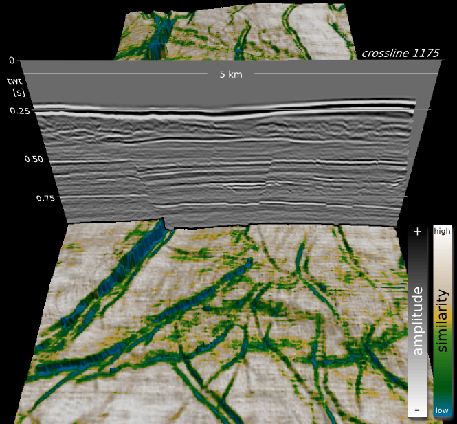
Hart (2013). ©SEG/AAPGForward modeling of seismic data is the most important workflow that nobody does.

Why is it important?

  • Communicate with your team. You know your seismic has a peak frequency of 22 Hz and your target is 15–50 m thick. Modeling can help illustrate the likely resolution limits of your data, and how much better it would be with twice the bandwidth, or half the noise.
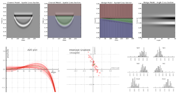
  • Calibrate your attributes. Sure, the wells are wet, but what if they had gas in that thick sand? You can predict the effects of changing the lithology, or thickness, or porosity, or anything else, on your seismic data.
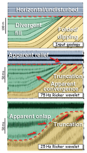
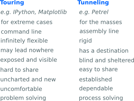
  • Calibrate your intuition. Only by predicting the seismic reponse of the geology you think you're dealing with, and comparing this with the response you actually get, can you start to get a feel for what you're really interpreting. Viz Bruce Hart's great review paper we mentioned last year (right).

Why does nobody do it?

Well, not 'nobody'. Most interpreters make 1D forward models — synthetic seismograms — as part of the well tie workflow. Model gathers are common in AVO analysis. But it's very unusual to see other 2D models, and I'm not sure I've ever seen a 3D model outside of an academic environment. Why is this, when there's so much to be gained? I don't know, but I think it has something to do with software.

  • Subsurface software is niche. So vendors are looking at a small group of users for almost any workflow, let alone one that nobody does. So the market isn't very competitive.
  • Modeling workflows aren't rocket surgery, but they are a bit tricky. There's geology, there's signal processing, there's big equations, there's rock physics. Not to mention data wrangling. Who's up for that?
  • Big companies tend to buy one or two licenses of niche software, because it tends to be expensive and there are software committees and gatekeepers to negotiate with. So no-one who needs it has access to it. So you give up and go back to drawing wedges and wavelets in PowerPoint.

Okay, I get it, how is this helping?

We've been busy lately building something we hope will help. We're really, really excited about it. It's on the web, so it runs on any device. It doesn't cost thousands of dollars. And it makes forward models...

That's all I'm saying for now. To be the first to hear when it's out, sign up for news here:

This will add you to the email list for the modeling tool. We never share user details with anyone. You can unsubscribe any time.

Seismic models: Hart, BS (2013). Whither seismic stratigraphy? Interpretation, volume 1 (1). The image is copyright of SEG and AAPG.

Which brittleness index?

A few weeks ago I looked at the concept — or concepts — of brittleness. There turned out to be lots of ways of looking at it. We decided to call it a rock behaviour rather than a property. And we determined to look more closely at some different ways to define it. Here they are...

Some brittleness indices

There are lots of 'definitions' of brittleness in the literature. Several of them capture the relationship between compressive and tensile strength, σC and σT respectively. This is potentially useful, because we measure uniaxial compressive strength in the standard triaxial rig tests that have become routine in shale studies... but we don't usually find the tensile strength, because it's much harder to measure. This is unfortunate, because hydraulic fracturing is initially a tensile failure (though reactivation and other failure modes do occur — see Williams-Stroud et al. 2012).

Altindag (2003) gave the following three examples of different brittleness indices. In turn, they are the strength ratio, a sort of relative strength contrast, and the mean strength (his favourite):

This is just the start, once you start digging, you'll find lots of others. Like Hucka & Das's (1974) round-up I wrote about last time, one thing they have in common is that they capture some characteristic of rock failure. That is, they do not rely on implicit rock properties.

Another point to note. Bažant & Kazemi (1990) gave a way to de-scale empirical brittleness measures to account for sample size — not surprisingly, this sort of 'real world adjustment' starts to make things quite complicated. Not so linear after all.

What not to do

The prevailing view among many interpreters is that brittleness is proportional to Young's modulus and/or Poisson's ratio, and/or a linear combination of these. We've reported a couple of times on what Lev Vernik (Marathon) thinks of the prevailing view: we need to question our assumptions about isotropy and linear strain, and computing shale brittleness from elastic properties is not physically meaningful. For one thing, you'll note that elastic moduli don't have anything to do with rock failure.

The Young–Poisson brittleness myth started with Rickman et al. 2008, SPE 115258, who presented a rather ugly representation of a linear relationship (I gather this is how petrophysicists like to write equations). You can see the tightness of the relationship for yourself in the data.

If I understand  the notation, this is the same as writing B = 7.14E – 200ν + 72.9, where E is (static) Young's modulus and ν is (static) Poisson's ratio. It's an empirical relationship, based on the data shown, and is perhaps useful in the Barnett (or wherever the data are from, we aren't told). But, as with any kind of inversion, the onus is on you to check the quality of the calibration in your rocks. 

What's left?

Here's Altindag (2003) again:

Brittleness, defined differently from author to author, is an important mechanical property of rocks, but there is no universally accepted brittleness concept or measurement method...

This leaves us free to worry less about brittleness, whatever it is, and focus on things we really care about, like organic matter content or frackability (not unrelated). The thing is to collect good data, examine it carefully with proper tools (Spotfire, Tableau, R, Python...) and find relationships you can use, and prove, in your rocks.

References

Altindag, R (2003). Correlation of specific energy with rock brittleness concepts on rock cutting. The Journal of The South African Institute of Mining and Metallurgy. April 2003, p 163ff. Available online.

Hucka V, B Das (1974). Brittleness determination of rocks by different methods. Int J Rock Mech Min Sci Geomech Abstr 10 (11), 389–92. DOI:10.1016/0148-9062(74)91109-7.

Rickman, R, M Mullen, E Petre, B Grieser, and D Kundert (2008). A practical use of shale petrophysics for stimulation design optimization: all shale plays are not clones of the Barnett Shale. SPE 115258, DOI: 10.2118/115258-MS.

Williams-Stroud, S, W Barker, and K Smith (2012). Induced hydraulic fractures or reactivated natural fractures? Modeling the response of natural fracture networks to stimulation treatments. American Rock Mechanics Association 12–667. Available online.

Seismic quality traffic light

We like to think that our data are perfect and limitless, because experiments are expensive and scarce. Only then can our interpretations hope to stand up to even our own scrutiny. It would be great if seismic data was a direct representation of geology, but it never is. Poor data doesn't necessarily mean poor acquisition or processing. Sometimes geology is complex!

In his book First Steps in Seismic Interpretation, Don Herron describes a QC technique of picking a pseudo horizon at three different elevations to correspond to poor, fair, and good data regions. I suppose that will do in a pinch, but I reckon it would take a long time, and it is rather subjective. Surely we can do better?

Computing seismic quality

Conceptually speaking, the ease of interpretation depends on things we can measure (and display), like coherency, bandwidth, amplitude strength, signal-to-noise, and so on. There is no magic combination of filters that will work for all data, but I am convinced that for every seismic dataset there is a weighted function of attributes that can be concocted to serve as a visual indicator of the data complexity:

So one of the first things we do with new data at Agile is a semi-quantitative assessment of the likely ease and reliability of interpretation.

This traffic light display of seismic data quality, corendered here with amplitude, is not only a precursor to interpretation. It should accompany the interpretation, just like an experiment reporting its data with errors. The idea is to show, honestly and objectively, where we can trust eventual interpretations, and where they not well constrained. A common practice is to cherry pick specific segments or orientations that support our arguments, and quietly suppress those that don't. The traffic light display helps us be more honest about what we know and what we don't — where the evidence for our model is clear, and where we are relying more heavily on skill and experience to navigate a model through an area where the data is unclear or unconvincing.

Capturing uncertainty and communicating it in our data displays is not only a scientific endeavour, it is an ethical one. Does it change the way we look at geology if we display our confidence level alongside? 

Reference

Herron, D (2012). First Steps in Seismic Interpretation. Geophysical Monograph Series 16. Society of Exploration Geophysicists, Tulsa, OK.

The seismic profile shown in the figure is from the Kennetcook Basin, Nova Scotia. This work was part of a Geological Survey of Canada study, available in this Open File report.

Colouring maps

Over the last fortnight, I've shared five things, and then five more things, about colour. Some of the main points:

  • Our non-linear, heuristic-soaked brains are easily fooled by colour.
  • Lots of the most common colour bars (linear ramps, bright spectrums) are not good choices.
  • You can learn a lot by reading Robert Simmon, Matteo Niccoli, and others.

Last time I finished on two questions:

  1. How many attributes can a seismic interpreter show with colour in a single display?
  2. On thickness maps should the thicks be blue or red?

One attribute, two attributes

The answer to the first question may be a matter of personal preference. Doubtless we could show lots and lots, but the meaning would be lost. Combined red-green-blue displays are a nice way to cram more into a map, but they work best on very closely related attributes, such as seismic amplitude of three particular frequencies

Here's some seismic reflection data — the open F3 dataset, offshore Netherlands, in OpendTect

A horizon — just below the prominent clinoforms — is displayed (below, left) and coloured according to elevation, using one of Matteo's perceptual colour bars (now included in OpendTect!). A colour scale like this varies monotonically in hue and luminance.

Some of the luminance channel (sometimes called brightness or value) is showing elevation, and a little is being used up by the 3D shading on the surface, but not much. I think the brain processes this automatically because the 3D illusion is quite good, especially when the scene is moving. Elevation and shape are sort of the same thing, so we've still only really got one attribute. Adding contours is quite nice (above, middle), and only uses a narrow slice of the luminance channel... but again, it's the same data. Much better to add new data. Similarity (a member of the family that includes coherence, semblance, and so on) is a natural fit: it emphasizes a particular aspect of the shape of the surface, but which was measured independently of the interpretaion, directly from the data itself. And it looks awesome (above, right).

Three attributes, four

OK, we have elevation and/or shape, and similarity. What else can we add? Another intuitive attribute of seismic is amplitude (below, left) — closely related to the strength of the reflected energy. Two things: we don't trust amplitudes in areas with low fold — so we can mask those (below, middle). And we're only really interested in bright spots, so we can edit the opacity profile of the attribute and make low values transparent (below, right). Two more attributes — amplitude (with a cut-off that reflects my opinion of what's interesting — is that an attribute?) and fold.

Since we have only used one hue for the amplitude, and it was not in Matteo's colour bar, we can layer it on the original map without clobbering anything. Unfortunately, there's no easy way for the low fold mask to modulate amplitude without interfering with elevation, because the elevation map needs to be almost completely opaque. What I need is a way to modulate a surface's opacity with an attribute it is not displaying with hue...

Thickness maps

The second question — what to colour thicks — is easy. Thicks should be towards the red end of the spectrum, sometimes not-necessarily-intuitively called 'warm' colours. (As I mentioned before in the comments, a quick Google image poll suggests that about 75% of people agree). If you colour your map otherwise, perhaps because you like the way it suggests palaeobathymetry in some depositional settings, be careful to make this very clear with labels and legends (which you always do anyway, right?). And think about just making a 'palaeobathymetry' map, not a thickness map.

I suspect there are lots of quite personal opinions out there. Like grammar, I do think much of this is a matter of taste. The only real test is clarity. Do you agree? Is there a right and wrong here? 

Well-tie workflow

We've had a couple of emails recently about well ties. Ever since my days as a Landmark workflow consultant, I've thought the process of calibrating seismic data to well data was one of the rockiest parts of the interpretation workflow—and not just because of SynTool. One might almost call the variety of approaches an unsolved problem.

Tying wells usually involves forward modeling a synthetic seismogram from sonic and density logs, then matching that synthetic to the seismic reflection data, thus producing a relationship between the logs (measured in depth) and the seismic (measured in travel time). Problems arise for all sorts of reasons: the quality of the logs, the quality of the seismic, confusion about handling the shallow section, confusion about integrating checkshots, confusion about wavelets, and the usability of the software. Like much of the rest of interpretation, there is science and judgment in equal measure. 

Synthetic seismogram (right) from the reservoir section of the giant bitumen field Surmont, northern Alberta. The reservoir is only about 450 m deep, and about 70 m thick. From Hall (2009), Calgary GeoConvention. 

Synthetic seismogram (right) from the reservoir section of the giant bitumen field Surmont, northern Alberta. The reservoir is only about 450 m deep, and about 70 m thick. From Hall (2009), Calgary GeoConvention

I'd go so far as to say that I think tying wells robustly is one of the unsolved problems of subsurface geoscience. How else can we explain the fact that any reasonably mature exploration project has at least 17 time-depth curves per well, with names like JLS_2002_fstk01_edit_cks_R24Hz_final?

My top tips

First, read up. White & Simm (2003) in First Break21 (10) is excellent. Rachel Newrick's essays in 52 Things are essential. Next, think about the seismic volume you are trying to tie to. Keep it to the nears if possible (don't use a full-angle stack unless it's all you have). Use a volume with less filtering if you have it (and you should be asking for it). And get your datums straight, especially if you are on land: make certain your seismic datum is correct. Ask people, look at SEGY headers, but don't be satisfied with one data point.

Once that stuff is ironed out:

  1. Chop any casing velocities or other non-data off the top of your log.
  2. Edit as gently and objectively as possible. Some of those spikes might be geology.
  3. Look at the bandwidth of your seismic and make an equivalent zero-phase wavelet.
  4. Don't extract a wavelet till you have a few good ties with a zero-phase wavelet, then extract from several wells and average. Extracting wavelets is a whole other post...
  5. Bulk shift the synthetic (e.g. by varying the replacement velocity) to make a good shallow event tie.
  6. Stretch (or, less commonly, squeeze) the bottom of the log to match the deepest event you can. 
  7. If possible, don't add any more tie points unless you really can't help yourself. Definitely no more than 5 tie points per well, and no closer than a couple of hundred milliseconds.
  8. Capture all the relevant data for every well as you go (screenshot, replacement velocity, cross-correlation coefficient, residual phase, apparent frequency content).
  9. Be careful with deviated wells; you might want to avoid tying the deviated section entirely and use verticals instead. If you go ahead, read your software's manual. Twice.
  10. Do not trust any checkshot data you find in your project — always go back to the original survey (they are almost always loaded incorrectly, mainly because the datums are really confusing).
  11. Get help before trying to load or interpret a VSP unless you really know what you are doing.

I could add some don'ts too...

  • Don't tie wells to 2D seismic lines you have not balanced yet, unless you're doing it as part of the process of deciding how to balance the seismic. 
  • Don't create multiple, undocumented, obscurely named copies or almost-copies of well logs and synthetics, unless you want your seismic interpretation project to look like every seismic interpretation project I've ever seen (you don't).

Well ties are one of those things that get in the way of 'real' (i.e. fun) interpretation so they sometimes get brushed aside, left till later, rushed, or otherwise glossed over. Resist at all costs. If you mess them up and don't find out till later, you will be very sad, but not as sad as your exploration manager.

Update

on 2013-04-27 13:25 by Matt Hall

Can't resist posting this most excellent well tie. Possibly the best you'll ever see.

Picture by Maitri, licensed CC-BY-NC-SA

Update

on 2014-07-04 13:53 by Matt Hall

Evan has written a deconstructed well-tie workflow, complete with IPython Notebook for you to follow along with, for The Leading Edge. Read Well-tie calculus here.

The elements of seismic interpretation

I dislike the term seismic interpretation. There. I said it. Not the activity itself, (which I love), just the term. Why? Well, I find it's too broad to describe all of the skills and techniques of those who make prospects. Like most jargon, it paradoxically confuses more than it conveys. Instead, use one of these three terms to describe what you are actually doing. Note: these tasks may be performed in series, but not in parallel.

Visualizing

To visualize is to 'make something visible to the eye'. That definition fits pretty well in what we want to do. We want to see our data. It sounds easy, but it is routinely done poorly. We need context for our data. Being able to change the way our data looks, exploring and exaggerating different perspectives and scales, symbolizing it with perceptually pleasant colors, displaying it alongside other relevant information, and so on.

Visualizing also means using seismic attributes. Being clever enough to judge which ones might be helpful, and analytical enough to evaluate from the range of choices. Even more broadly, visualizing is something that starts with acquisition and survey planning. In fact, the sum of processes that comprise the seismic experiment is to make the unseen visible to the eye. I think there is a lot of room left for bettering our techniques of visualization. Steve Lynch is leading the way on that.

Digitizing

One definition of digitizing is along the lines of 'converting pictures or sound into numbers for processing in a computer'. In seismic interpretation, this usually means capturing and annotating lines, points, and polygons, for making maps. The seismic interpreter may spend the majority of their time picking horizons; a kind of computer-assisted drawing. Seismic digitization, however, is both guided and biased by human labor in order to delineate geologic features requiring further visualization. 

Whether you call it picking, tracking, correlating or digitizing, seismic interpretation always involves some kind of drawing. Drawing is a skill that should be celebrated and practised often. Draw, sketch, illustrate what you see, and do it often. Even if your software doesn't let you draw it the way an artist should.

Modeling

The ultimate goal of the seismic interpreter, if not all geoscientists, is to unambiguously parameterize the present-day state of the earth. There is after all, only one true geologic reality manifested along only one timeline of events.

Even though we are teased by the sparse relics that comprise the rock record, the earth's dynamic history is unknowable. So what we do as interpreters is construct models that reflect the dynamic earth arriving at its current state.

Modeling is another potentially dangerous jargon word that has been tainted by ambiguity. But in the strictest sense, modeling defines the creative act of bringing geologic context to bear on visual and digital elements. Modeling is literally the process of constructing physical parameters of the earth that agree with all available observations, both visualized and digitized. It is the cognitive equivalent of solving a mathematical inverse problem. Yes, interpreters do inversions all the time, in their heads.

Good seismic interpretation requires practising each of these three elements. But indispensable seismic interpretation is achieved only when they are masterfully woven together.

Recommended reading
Steve Lynch's series of posts on wavefield visualization at 3rd Science is a good place to begin.

Making images or making prospects?

Well-rounded geophysicists will have experience in each of the following three areas: acquisition, processing, and interpretation. Generally speaking, these three areas make up the seismic method, each requiring highly specified knowledge and tools. Historically, energy companies used to control the entire spectrum, owning the technology, the know-how and the risk, but that is no longer the case. Now, service companies do the acquisition and the processing. Interpretation is largely hosted within E & P companies, the ones who buy land and drill wells. Not only has it become unreasonable for a single geophysicist to be proficient across the board, but organizational structures constrain any particular technical viewpoint. 

Aligning with the industry's strategy, if you are a geophysicist, you likely fall into one of two camps: those who make images, or those who make prospects. One set of people to make the data, one set of people to do the interpretation.

This seems very un-scientific to me.

Where does science fit in?

Science, the standard approach of rational inquiry and accruing knowledge, is largely vacant from the applied geophysical business landscape. But, when science is used as a model, making images and making prospects are inseperable.

Can applied geophysics use scientific behaviour as a central anchor across disciplines?

There is a significant amount of science that is needed in the way that we produce observations, in the way that we make images. But the business landscape built on linear procedures leaves no wiggle room for additional testing and refinement. How do processors get better if they don't hear about their results? As a way of compensating, processing has deflected away from being a science of questioning, testing, and analysis, and moved more towards, well,... a process.

The sure-fire way to build knowledge and decrease uncertainty, is through experimentation and testing. In this sense this notion of selling 'solutions', is incompatible with scientific behavior. Science doesn't claim to give solutions, science doesn't claim to give answers, but it does promise to address uncertainty; to tell you what you know.

In studying the earth, we have to accept a lack of clarity in our data, but we must not accept mistakes, errors, or mediocrity due to shortcomings in our shared methodologies.

We need a new balance. We need more connectors across these organizational and disciplinary divides. That's where value will be made as industry encounters increasingly tougher problems. Will you be a connector? Will you be a subscriber to science?

Hall, M (2012). Do you know what you think you know? CSEG Recorder 37 (2), February 2012, p 26–30. Free to download from CSEG. 

5 ways to kickstart an interpretation project

Last Friday, teams around the world started receiving external hard drives containing this year's datasets for the AAPG's Imperial Barrel Award (IBA for short). I competed in the IBA in 2008 when I was a graduate student at the University of Alberta. We were coached by the awesome Dr Murray Gingras (@MurrayGingras), we won the Canadian division, and we placed 4th in the global finals. I was the only geophysical specialist on the team alongside four geology graduate students.

Five things to do

Whether you are a staff geoscientist, a contractor, or competitor, it can help to do these things first:

  1. Make a data availability map (preferably in QGIS or ArcGIS). A graphic and geospatial representation of what you have been given.
  2. Make well scorecards: as a means to demonstrate not only that you have wells, but what information you have within the wells.
  3. Make tables, diagrams, maps of data quality and confidence. Indicate if you have doubts about data origins, data quality, interpretability, etc.
  4. Background search: The key word is search, not research. Use Mendeley to organize, tag, and search through the array of literature
  5. Use Time-Scale Creator to make your own stratigraphic column. You can manipulate the vector graphic, and make it your own. Much better than copying an old published figure. But use it for reference.

All of these things can be done before assigning roles, before saying who needs to do what. All of this needs to be done before the geoscience and the prospecting can happen. To skirt around it is missing the real work, and being complacent. Instead of being a hammer looking for a nail, lay out your materials, get a sense of what you can build. This will enable educated conversations about how you can spend your geoscientific manpower, division of labour, resources, time, etc.

Read more, then go apply it 

In addition to these tips for launching out of the blocks, I have also selected and categorized blog posts that I think might be most relevant and useful. We hope they are helpful to all geoscientists, but especially for students. Visit the Agile blog highlights list on SubSurfWiki.

I wish a happy and exciting IBA competition to all participants, and their supporting university departments. If you are competing, say hi in the comments and tell us where you hail from. 

Swimming in acronym soup

In a few rare instances, an abbreviation can become so well-known that it is adopted into everyday language; more familar than the words it used to stand for. It's embarrasing, but I needed to actually look up LASER, and you might feel the same way with SONAR. These acronyms are the exception. Most are obscure barriers to entry in technical conversations. They can be constructs for wielding authority and exclusivity. Welcome to the club, if you know the password.

No domain of subsurface technology is riddled with more acronyms than well log analysis and formation evaluation. This is a big part of — perhaps too much of a part of — why petrophysics is hard. Last week, I came across a well. It has an extended suite of logs, and I wanted make a synthetic. Have a glance at the image and see which curve names you recognize (the size represents the frequency the names are encountered across many files of the same well).

I felt like I was being spoken to by some earlier deliquent: I got yer well logs right here buddy. Have fun sorting this mess out.

The log ASCII standard (*.LAS file) file format goes a long way to exposing descriptive information in the header. But this information is often incomplete, missing, and says nothing about the quality or completeness of the data. I had to scan 5 files to compile this soup. A micro-travesty and a failure, in my opinion. How does one turn this into meaningful information for geoscience?

Whose job is it to sort this out? The service company that collected the data? The operator that paid for it? A third party down the road?

What I need is not only an acronym look-up table, but also a data range tool to show me what I've got in the file (or files), and at which locations and depths I've got it. A database to give me more information about these acronyms would be nice too, and a feature that allows me to compare multiple files, wells, and directories at once. It would be like a life preserver. Maybe we should build it.

I made the word cloud by pasting text into wordle.net. I extracted the text from the data files using the wonderful LASReader written by Warren Weckesser. Yay, open source!

Touring vs tunnel vision

My experience with software started, and still largely sits, at the user end. More often than not, interacting with another's design. One thing I have learned from the user experience is that truly great interfaces are engineered to stay out of the way. The interface is only a skin atop the real work that software does underneath — taking inputs, applying operations, producing outputs. I'd say most users of computers don't know how to compute without an interface. I'm trying to break free from that camp. 

In The dangers of default disdain, I wrote about the power and control that the technology designer has over his users. A kind of tunnel is imposed that restricts the choices for interacting with data. And for me, maybe for you as well, the tunnel has been a welcome structure, directing my focus towards that distant point; the narrow aperture invokes at least some forward motion. I've unknowingly embraced the tunnel vision as a means of interacting without substantial choices, without risk, without wavering digressions. I think it's fair to say that without this tunnel, most travellers would find themselves stuck, incapacitated by the hard graft of touring over or around the mountain.

Tour guides instead of tunnels

But there is nothing to do inside the tunnel, no scenery to observe, just a black void between input and output. For some tasks, taking the tunnel is the only obvious and economic choice — all you want is to get stuff done. But choosing the tunnel means you will be missing things along the way. It's a trade off.

For getting from A to B, there are engineers to build tunnels, there are travellers to travel the tunnels, and there is a third kind of person altogether: tour guides take the scenic route. Building your own tunnel is a grand task, only worthwhile if you can find enough passengers to use it. The scenic route isn't just a casual lackadaisical approach. It's necessary for understanding the landscape; by taking it the traveler becomes connected with the territory. The challenge for software and technology companies is to expose people to the richness of their environment while moving them through at an acceptable pace. Is it possible to have a tunnel with windows?

Oil and gas operating companies are good at purchasing the tunnel access pass, but are not very good at building a robust set of tools to navigate the landscape of their data environment. After all, that is the thing that we travellers need to be in constant contact with. Touring or tunneling? The two approaches may or may not arrive at the same destination and they have different costs along the way, making it different business.